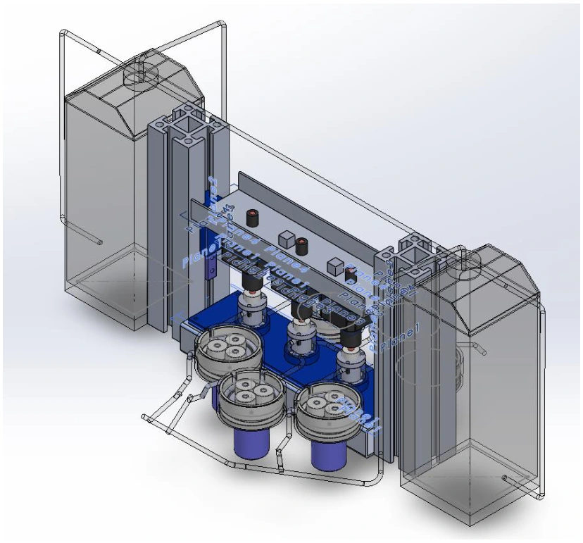
Designing a bioreactor for bone tissue.
Our group designed a bioreactor that would push culture fluid through a scaffold while applying compression. We developed a three-chamber concept so several samples could be handled in the same system.
I led the concept development and helped work out what the system needed to do. My main technical work was on the scaffold, its pore sizes and sensing. The pump, chambers and compression mechanism were other team members’ areas.
Choosing how it would work.
We considered several concepts before settling on the multi-chamber design. We wanted to handle samples in parallel and combine fluid delivery with mechanical loading in one assembly.
Peristaltic pumps drove the proposed closed-loop perfusion network. The chamber concept used bottom-to-top flow through the scaffold, with seals and removable components forming part of the mechanical design.
My part: the scaffold.
The final report specifies a cylindrical scaffold 10 mm in diameter and 10 mm high, with a selected design porosity of 65.5% and approximately 300–600 μm pores. These were design choices intended to balance transport through the scaffold with mechanical support.
I had to think about the pore sizes alongside the flow, pressure sensing and chamber design. Changing the scaffold would affect what the pump needed to deliver and how it fitted with the compression mechanism.
10 mm diameter × 10 mm height · 65.5% selected porosity · Approximately 300–600 μm pores.
The 3D model didn’t converge.
We initially tried a full 3D scaffold-flow model, but ran into meshing and convergence problems. We moved to a 2D representation so we could investigate the flow and wall shear stress with a model we could get to solve.
That let us look at the flow around the scaffold features, but it left out the full 3D pore network. I treat these as results from a simplified model, rather than proof of how a manufactured scaffold would perform.
What the work delivered.
By the end, we had a full CAD concept, component and material choices, and flow and compression studies. My scaffold work had to fit into that bigger design, rather than just look reasonable on its own.
I learned a lot from working through those connections with the team, and from deciding what we could reasonably learn from a simpler model.
A note on the analysis
65.5% is the design porosity stated in our report; I haven’t independently checked it from CAD here. Some values in the report text differ from the CFD figure scales, and the compression table doesn’t fully agree with the later linearity discussion. I’ve kept those limits visible rather than using the disputed numbers as performance claims. This was a design and simulation project, without biological testing.